Pcb Design Pdf Free Download
Top 30 Best Free PCB Design Software Download
There are many printed circuit board design software available to satisfy diversified layout requirements, including free PCB design software, online free PCB design software, and industrial PCB design software. This is the PCB design software list and brief introduction. You can have a comparison based on the introduction.
PCB Design Software Free Download
This is a comparison of several PCB design software. They all meet the criteria below:
- They have a free version available.
- The free version is time unlimited.
- This free version can provide schematic & circuit board design and generate the form for PCB manufacturing.
- The software is being actively developed and supported.
Free PCB Design Software List
1. PartSim
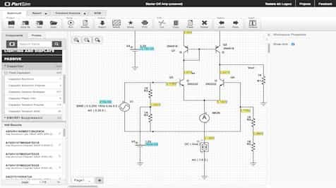
PartSim is a free and easy-to-use circuit simulator that includes a full SPICE simulation engine, a web-based schematic capture tool, a graphical waveform viewer, and Digi-Key that runs in your web browser. PartSim consists of an integrated Bill-Of-Materials manager that lets you assign Digi-Key Part Numbers to your models.
Features:
- SPICE Simulator
- AC/DC/Transient Sims
- Waveform Viewer
Types: Online Free PCB Design Software
2. Scheme-it
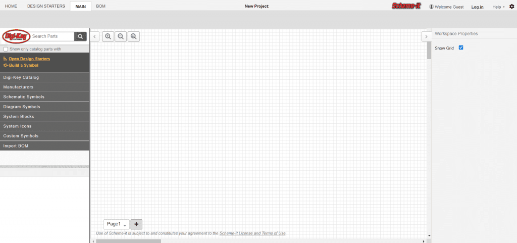
Scheme-it is a free online schematic and diagramming tool that allows anyone to design and share electronic circuit diagrams. The tool includes a comprehensive electronic symbol library and an integrated Digi-Key component catalog that allows for various circuit designs. Additionally, a built-in bill of materials manager is provided to keep track of parts used in a design. Once a schematic drawing is complete, users can export it to an image file or share it via email with others. Scheme-it works natively in all major web browsers without requiring the use of any plugins. Only registered users can share and save designs.
Features:
- Ability to diagram at the Block, Icon, System, or Schematic level.
- A library of over 700 generic symbols, as well as custom symbol creation.
- Access to over 4 million components via Digi-Key Catalog integration.
- Freedom to keep designs private, make public, share via link, or embed web pages, blogs, or emails.
- Rapid design evolution via Bill of Material (BOM) import capability.
- Integrated Bill of Materials and quoting.
- Export into PDF or PNG files.
- A direct link to Digi-Key Technical Support for help with component selection activities.
Type: Online Free PCB Design Software
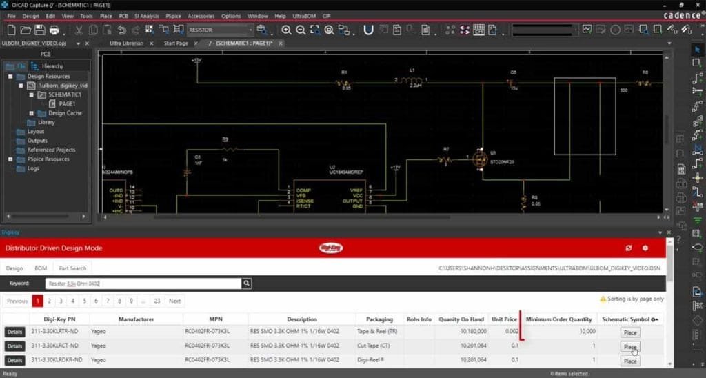
3. Ultra Librarian
Features:
- Automated and Manual Footprint, Symbol, and 3D Model Creation
- Access to Database of Pre-Built Library Parts that export to most CAD formats
- Integrated Verification System throughout
- Component Database System
- Footprint Database System
- Component Intelligence
Notes:
- Free Online PCB CAD Library
- World's Largest PCB CAD Library
- Vendor-neutral data for ECAD design, simulation and 3D modeling.
Accelerated Designs focuses on providing Electronic Component Manufacturers and Engineers with vendor-neutral data for ECAD design, simulation, and 3D modeling. The flagship product of Accelerated Designs is the Ultra Librarian, which creates and exports vendor-neutral ECAD data in a format that over 22 different CAD tools can consume. With the Ultra Librarian, automation is key – build your component accurately one time and export to the CAD tool(s) of your choice! We also provide the industry's most extensive library of pre-built ECAD components – currently at 7.2 million parts and growing monthly. This library represents over 400 manufacturers, and 82% of these components can dynamically create 3D STEP models. With Part Packs available in two different sizes or a yearly subscription, you can get all the component data you need!
Accelerated Designs offers the fastest & most accurate library management tool in the printed circuit board industry. Our goal is to provide a one-stop source of data for all CAD design, simulation, 3D modeling, and other engineering data in a form that is entirely customizable to meet your company's requirements as well as fulfill your clients' needs.
With Ultra Librarian, You Can
1. Search
Quickly find the parts you need in our ever-expanding database of verified parts from the leading component manufacturers.
2. Download
Unlimited access to FREE schematic symbols, PCB footprints, and 3D STEP models in your native CAD format.
3. Design
With your part, the library needs to get back to focusing on what matters, designing revolutionary electronics.
4. Autodesk Circuits
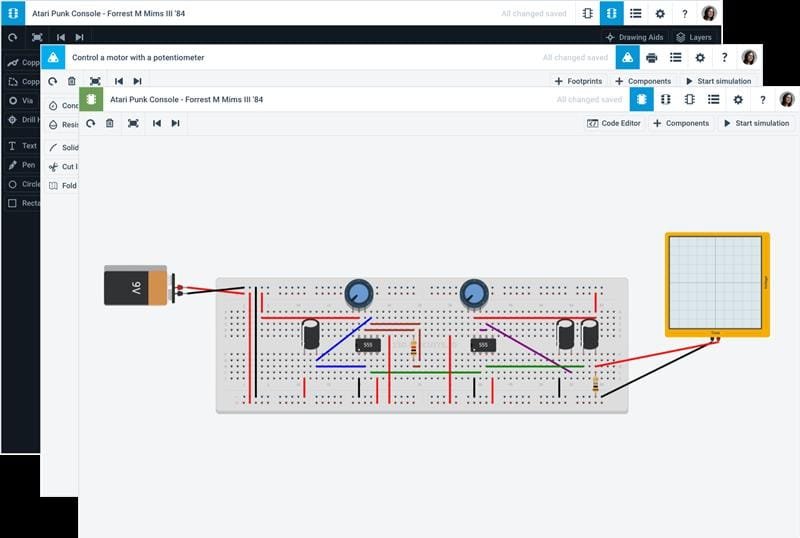
Autodesk Circuits empowers you to bring your ideas to life with free, easy-to-use online tools. You can start with simple experiments in the Electronics Lab or Circuit Scribe if you are a beginner. Experienced users can skip ahead and go straight to PCB Design.
- Simulate and program Arduino and breadboard components
- Use standard modules to build complex circuits
- Create and explore circuits, then export to PCB design software
Notes: Web-based app. The free version makes your designs public.
Output Gerbers: Yes
5. CircuitMaker

Altium builds CircuitMaker, so you can have complete confidence in the technology that drives most of the world's PCB design activity.
CircuitMaker is the best free-to-use schematic and PCB design tool for the Open Source Hardware community.
CircuitMaker is not just a free EDA software tool from Altium; it's also a community of creative people and design content, working together to invent circuits and electronics products for a better future.
For turning great ideas into real products, you need design tools that won't limit your imagination or hold you back. CircuitMaker has all the power you need to design high-quality schematics and Printed Circuit Boards, with no artificial limits on layer counts or board area.
CircuitMaker is more than just a free schematic and PCB design tool – it's a vibrant community of open source designers, makers, hobbyists, students, and professionals working together to make exciting new products every day.
Output Gerbers: Yes

Recommended PCB Manufacturing Services
6. SoloPCB Design
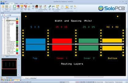
SoloPCB Design software consisting of schematic capture, PCB layout, and integrated auto-routing – supporting a broad range of capabilities from single-sided PCBs with jumpers to high layer count PCBs with advanced technologies. Solo PCB Design delivers unrestricted full-featured capability.
The ease-of-use and intuitive design provide for quick start-up and rapid learning. The flexible design environment offers the DIY engineer multiple ways to drive your PCB design project from a schematic-driven approach using SoloCapture's hierarchal circuit editor to an on-the-fly PCB layout within the SoloPCB Editor without a schematic. SoloPCB Design works the way you want to work.
We partner with industry-leading PCB manufacturers worldwide to give you the largest selection of manufacturing options for your PCB project. We integrate each manufacturing partner's design rules right into the software and automate the transfer of your manufacturing data to help ensure your PCBs are built without delay or defect.
The SoloPCB Design software delivers features and functionality typically only found only in commercial Electronic Design Automation (EDA) tools.
Notes: Usable only with licensed manufacturers
Output Gerbers: Yes
7. MultiSIM BLUE 14
NI Multisim 14 represents a best-in-class engineering design experience, both in the classroom and laboratory, performing SPICE simulation or measurements on prototypes. With strong roots as an exploratory virtual electronics workbench, Multisim has been a primary go-to tool for students and engineers to investigate and implement their new circuit designs and electronic inventions.
System Requirements for MultiSIM BLUE
- Windows Operating System
- Pentium 4/M class microprocessor or equivalent
- 512 MB of memory (256 MB minimum)
- 2 GB of free hard disk space
- Open GL capable 3D graphics card recommended (SVGA resolution video adapter with 800 × 600 video resolution minimum, 1024 × 768 or higher preferred)
Supported Operating System Requirements
- Windows 7 SP1 (32-bit and 64-bit)
- Windows Server 2008 R2 (64-bit)
- Windows 8.1 (32-bit and 64-bit)
- Windows Server 2012 R2 (64-bit)
- Windows 10 (32-bit and 64-bit)
8. Target 3001! PCB-POOL Edition
Use TARGET 3001! PCB-POOL®-Edition! The full range of design capability for PCB-POOL® customers. It's free!
TARGET 3001! PCB-POOL®-Edition
- all functions active (PCB and front panel) – equal to edition professional
- production data limited to production with PCB-POOL® resp. PANEL-POOL®
- project files (*.T3000) not compatible with regular TARGET editions (*.T3001).
- PCB: Unlimited # of pins and pads
- Front panel: Unlimited tool moves
- 100 copper layers
- 100 signals simulatable
- 78″ x 78″ board size
- Component database: unlimited access
- PCB printing enabled, including 100% scale
- PCB-POOL® and PANEL-POOL® price calculator
- Assembly tool plus price calculator
- MID design supported
- PCB-Layout
- PCB Simulation
- Schematic Capture
- Auto-placer
- Auto-router
- EMC Analysis
- Integrated assembly calculation
- Online ordering facility
9. PCBWeb
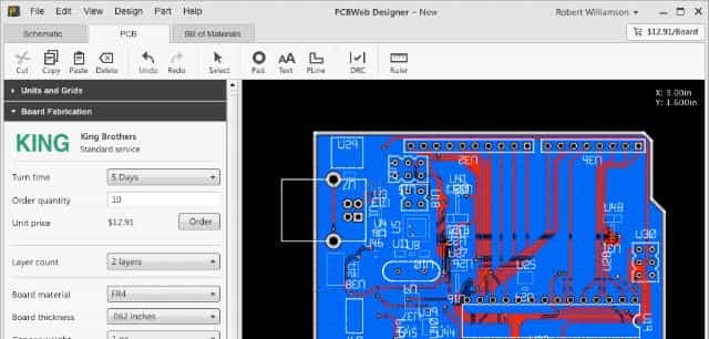
PCBWeb is a free online CAD application used to design and manufacture electronics hardware integrated with DigiKey's component catalog and BOM manager.
System Requirements for PCBWeb:
- Windows Operating System
- Windows 7(32-bit and 64 bit)
- Windows 8
- Windows 8.1
- Windows 10
- Directx 11 and MSAA support for video adapters
10. Osmond PCB
Printed Circuit Board Design for Macintosh – Design Without Restrictions
If you design printed circuit boards, or you would like to, Osmond PCB for Macintosh puts excellent power and flexibility within your reach. Artificial limits and restrictions are banished. You can now design boards of any size and shape and with as many layers as you want. Osmond gives you all the precision you need with a spatial resolution of 10 nanometers (0.00001 mm). You can place parts anywhere on the board with any orientation. You can also run traces of any width along any path and at any angle.
Osmond has tools that let you check that your design is free from error and meets all your specified design rules.
Once your design is complete, Osmond can produce standard Gerber (RS-274X) files and Excellon drill files that fabricators use to make your boards. If you desire more control over the fabrication process, Osmond will also let you define your panels containing multiple copies of your design or several different designs. Do-it-yourself fabricators may prefer Osmond's Postscript output, which can be directly printed on transparencies that can be used to etch the PC board.
Key Osmond Features
- Free (donations accepted)
- Any size, any shape
- Multiple Layers
- Thru-hole and Surface Mount Parts
- Design rule checks
- Metric and Imperial units
- Ground planes and copper flood
- Use any PDF file as the background
- Gerber and Drill file output
- PostScript and DXF file outputs
- Lua Scripting support
Limitations: pins: 700
11. EasyEDA
EasyEDA Has a Free Version for Everyone.
EasyEDA is a web-based EDA tool suite that enables hardware engineers to design, simulate, share – publicly and privately – and discuss schematics, simulations, and printed circuit boards. Other features include the creation of a Bill of Materials, Gerber, and pick and place files and documentary outputs in PDF, PNG, and SVG formats.
EasyEDA allows the creation and editing of schematic diagrams, SPICE simulation of mixed analog and digital circuits, and the creation and editing of printed circuit board layouts and, optionally, the manufacture of printed circuit boards.
Supported Operating System Requirements:
- Windows: Windows 7 and above(32-bit and 64-bit)
- Linux
- Mac
Online Editor and Desktop Client are available.
12. Fritzing
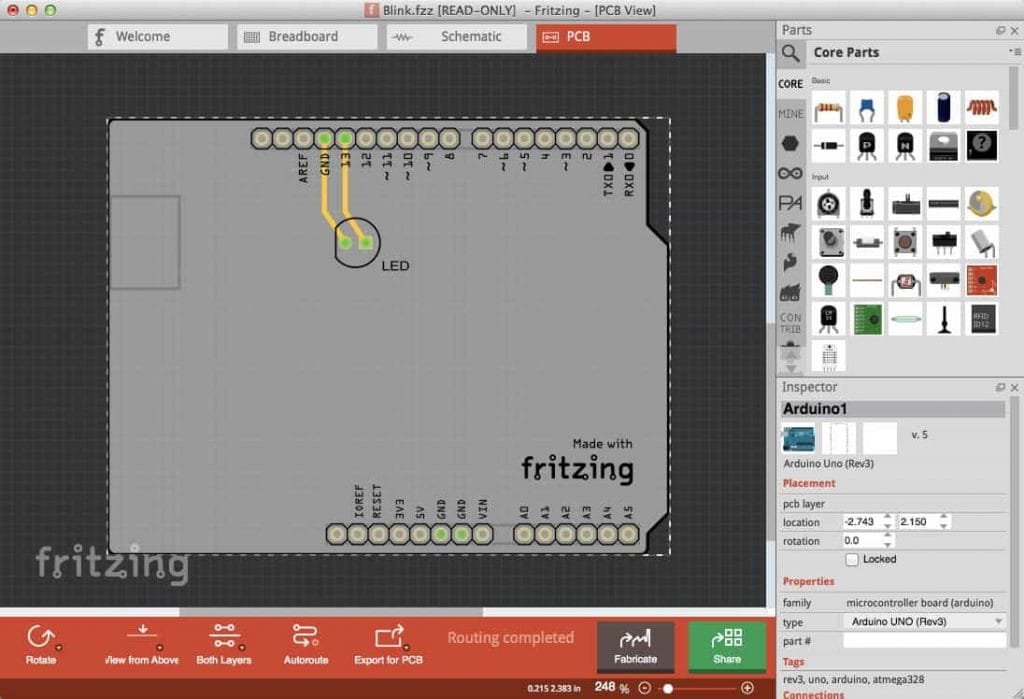
Fritzing is an open-source hardware initiative that makes electronics accessible as a creative material for anyone. We offer a software tool, a community website, and services in the spirit of Processing and Arduino, fostering a creative ecosystem that allows users to document their prototypes, share them with others, teach electronics in a classroom, and layout and manufacture professional PCBs.
Installing Fritzing
Please make sure your system satisfies one of these requirements:
- Windows 10 – Windows 7 was reported to work, too
- Mac – OSX 10.14 and up, though 10.13 might work too. MacOS 10.15 is currently untested.
- Linux – a fairly recent Linux distro with libc >= 2.6
- Start downloading the Fritzing package that's right for you.
- Unzip your Fritzing folder somewhere convenient on your hard drive.
This may also be a good time for you to create a shortcut to the Fritzing application. - To start Fritzing:
-
-
- on Windows: double-click fritzing.exe
- on Mac: double-click the Fritzing application
- on Linux: double-click Fritzing, or try ./Fritzing in your shell window
-
12. Fritzing
Fritzing is an open-source hardware initiative that makes electronics accessible as a creative material for anyone. We offer a software tool, a community website, and services in the spirit of Processing and Arduino, fostering a creative ecosystem that allows users to document their prototypes, share them with others, teach electronics in a classroom, and layout and manufacture professional PCBs.
Installing Fritzing
Please make sure your system satisfies one of these requirements:
- Windows 10 – Windows 7 was reported to work, too
- Mac – OSX 10.14 and up, though 10.13 might work too. MacOS 10.15 is currently untested.
- Linux – a fairly recent Linux distro with libc >= 2.6
- Start downloading the Fritzing package that's right for you.
- Unzip your Fritzing folder somewhere convenient on your hard drive.
This may also be a good time for you to create a shortcut to the Fritzing application. - To start Fritzing:
-
-
- on Windows: double-click fritzing.exe
- on Mac: double-click the Fritzing application
- on Linux: double-click Fritzing, or try ./Fritzing in your shell window
-
13. Target 3001! discover

TARGET 3001! is a CAD-/CAE-software for PCB design made in Germany by IBF.
It consists of schematic, simulation, layout, autorouter, 3D view, and front panel design within one user interface. There are price calculators, including ordering functions for PCB and front panels.
The external autorouter ELECTRA supplementary is embedded to every edition in a 250 pin-capable version. The complete project data are gathered in one central project file. No conversion struggles and no version conflicts between schematic and layout. TARGET 3001! provides manufacturing data for production processes of all industry standards.
TARGET 3001 V20 DISCOVER -250 Pins/Pads, two copper layers, area 2.0m x 2.0m, and much more: all functions active*, no time limit, no codes.
Just download and get started.
Limitations: layers: 2, pins: 250
14. PCB Artist
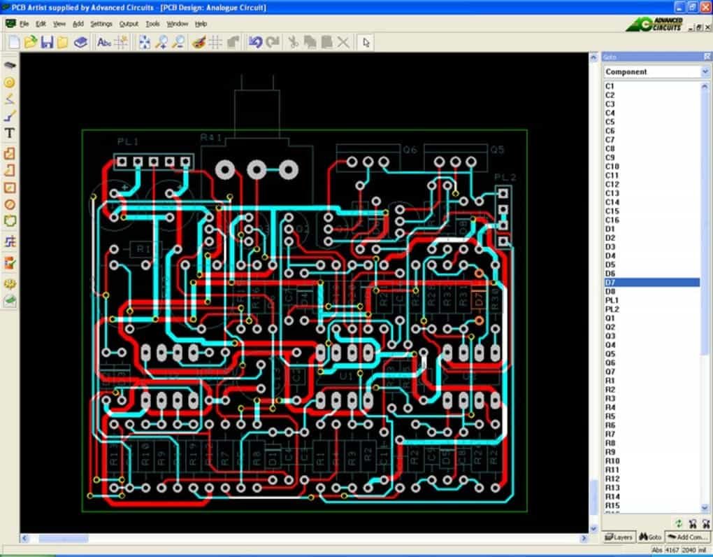
PCB Artist is a user-friendly, fully integrated schematic capture & Free PCB Layout Software that you will find easy to use. You can download PCB Artist, install the product at no charge, and start almost immediately designing your PCB design. The program has been specially developed to require no formal training or in-depth experience with PCB layout tools. Once complete, your files are saved to your computer, or you can upload and send them to us for order placement. There are tutorials to get started, and Gerber files are available with your order.
Operating Systems:
- Windows 10
- Windows 8
- Windows Vista
- Windows 7
- Windows XP
Limitations: Layers: 10
15. PCB123
ONE OF THE FIRST FREE-TO-USE PCB DESIGN TOOLS AVAILABLE.
PCB123 is a full-feature design tool for Printed Circuit Board designers of all levels. Introduced as a free tool in 2002, PCB123 still operates on a risk-sharing business model: We don't get paid until you succeed at designing your PCB. And to help ensure your success, we staff our technical support department with professionals that can answer your questions.
So what's to stop you? Easy-to-use and professional-grade PCB CAD software that's free and fully supported.
Available only for Windows environments.
Limitations:
- 6 Layers
- Usable only with Sunstone's manufacturing

16. Pad2Pad
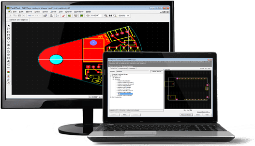
The free Pad2Pad CAD PCB layout software includes the easy-yet-powerful features you need to design your boards:
- Multiple pad types – single layer, multi-layer, vias, rectangular, round
- Variety of trace widths
- Footprints – library and custom
- Design rule checker
- Full control of PCB views and layers
- Move, rotate, delete objects
- Snap to grid and snap to angle
- Undo/Redo
- Geometric shapes: lines, arcs, circles, polygons
- Text with size and font control
- Ground plane wizard
- Logical connections (nets) – via dialog or GUI
- Auto-create nets from traces
- Auto Routing
- Component assembly
- Instant pricing
- Online ordering
Limitations
- 4 Layers
- Usable only with Pad2Pad's PCB manufacturing
17. ExpressPCB
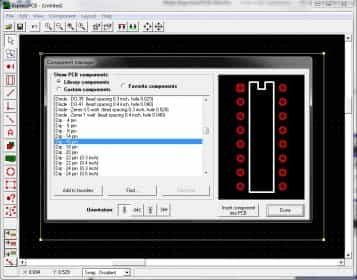
Laying out PCBs is easy, even for the first-time user. Both ExpressPCB tools are FREE to use, easy to learn.
ExpressPCB Classic
- 2 – 4 layers
- Silkscreen Top Layer
- Schematic Link To Layout
- Integrated Manufacturing
ExpressPCB Plus
- 2 – 6 layers
- Silkscreen 2 Sides (Top/Bottom)
- Copy & Paste Between Designs
- Integrated Manufacturing
18. CometCAD
CometCAD is a tool for creating circuit schematics and printed circuit boards (PCBs).
CometCAD is built for Windows and falls under a free-use license. The design of the PCB using this software is divided into three stages: symbols, circuits, and layout.
CometCAD is a circuit schematic and layout editor program for Windows 2k, XP, Vista, and 7.
Circuit Editor:
- multi-sheet circuit schematics
- maximum sheet size 2 m * 2 m
- symbol rotation with 90-degree steps
- netlist transfer to PCB (forward annotation)
- part list outputs
- SPICE netlist output
Layout (PCB) Editor:
- 1/2 copper layers
- internal resolution one micrometer
- maximum PCB size and number of package pins depends on the level
- copper planes and design rule checks
- possibility to adjust trace width between corner points
- component rotation with 90-degree steps
- CAM output (Gerber, drill, pick, and place) files
- PCB border can have a polygon shape
- milled PCB gaps/cuts and round holes are possible
- possibility to create rectangular multi-PCB panels
19. PCB Elegance
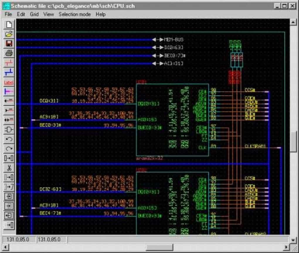
PCB Elegance is a suite of circuit board design tools for Windows. Including schematic capture, board layout, and manufacturing file generation. First released in 1998, it was proprietary software until 2012 when it was released as open-source software under the GPL.
Features
- Free and open source.
- Easy to learn. The user interface is logical, follows modern conventions, and is consistent across the different tools.
- Fast zoom and panning with the mouse.
- Able to handle complex designs. 2000+ components, 40000+ traces are no problem. A Pentium motherboard is included as an example design.
- Keyboard shortcuts are listed next to each menu item, so maybe learned as you go. They can also be modified.
- The colors of schematic and layout editors can be changed. Bicolored patterns are supported in the layout editor.
- Route with online DRC, active rats nest, trace dragging.
- Active schematic selection allows selecting groups of layout components from the schematic editor.
- Edit parameters of multiple components at once.
- Schematic symbol editor allows the creation of complex schematic symbols quickly.
- Symbol libraries are included.
- Geometry editor contains wizards for integrated circuits DIP, SOIC, BGA, etc.
Context-sensitive help. - Generates Gerber output plots.
20. OrCAD PCB Designer Lite
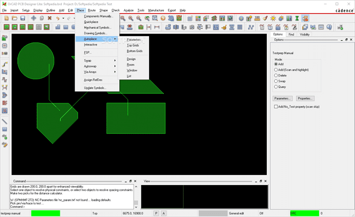
OrCAD PCB Designer Lite is a Cadence product that assists electrical engineers and layout designers produce Printed Circuit Boards, providing them with a state-of-the-art toolset that includes powerful editing and routing features.
OrCAD PCB Designer Lite is another successful release from Cadence that aims to encourage designers to value and materialize their ideas using a unique design technology that's interactive and productive.
The core of OrCAD PCB Designer Lite is the PCB Editor that arranges for the circuit to be automatically routed, connecting the components on the board wisely and correctly without tampering with your design.
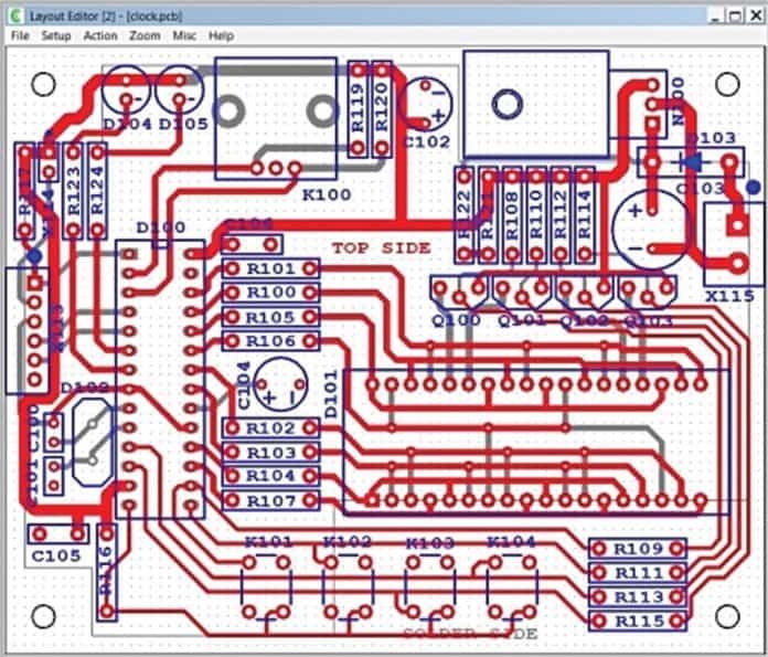
21. Layo1

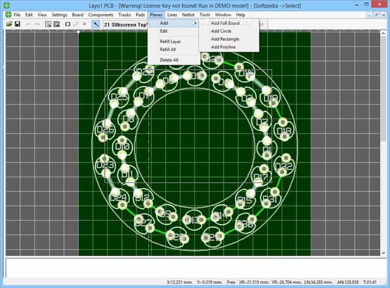
Specifications of Layo1 PCB
- Program and Help in multiple languages.
- Internal resolution: 0.0001 mm (0.1 micron)
- Maximum PCB design size: 2000 mm x 2000 mm
- Unlimited number of vectors per PCB design
- Documentation layers for silkscreen, soldering mask, soldering paste, assembly, etc.
- Unlimited number of track widths per PCB design (including on documentation layers)
- Unlimited number of pad definitions per PCB design
- Unlimited number of via definitions per PCB design
- Unlimited number of drilling diameters per PCB design
- Component rotation: 0.001 degrees
- Track/Pad definitions are stored in a library
- Layer colors can be set per PCB design
- Background colors can be set
- Colors of drilling holes can be set
- An unlimited number of track widths per network can be set
- Minimum/Maximum track width per net can be set
- Tables for display/modification of Netlist, components, pads, and layers, etc.
- Undo/Redo can be repeated up to 5 times
- Online DRC
- Rats nest remains visible and is updated automatically
- Copper-Pour (copper field)
- Automatic and adjustable number of spare files on separate drive or computer
- Online (context) sensitive Help
- Create an unlimited number of templates for personal settings
22. CADSTAR Express
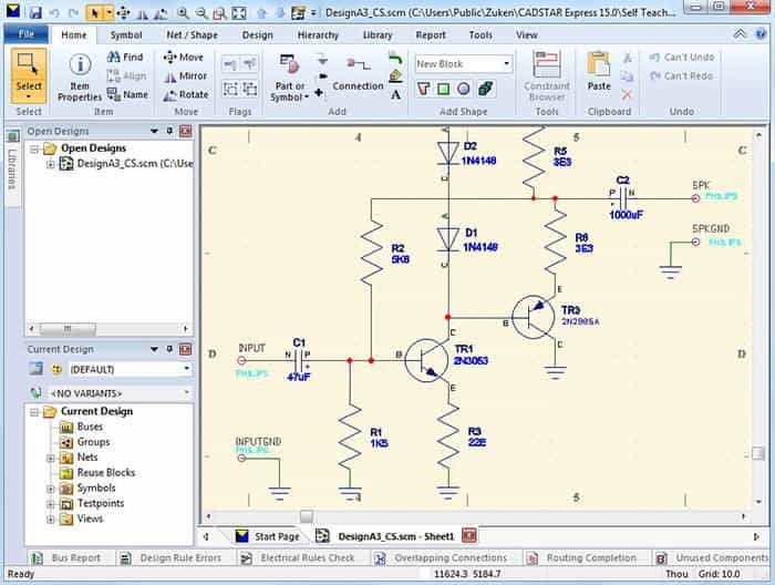
CADSTAR Express provides a quick and easy way for you to experience the basic features of our standard PCB solution. It includes all the functionality of CADSTAR 17.0, limited to 300 pins and 50 components, plus the opportunity to experience Zuken's advanced P.R.Editor XR 2000.
CADSTAR Express includes access to view a limited number of the 250,000+ parts available within the CADSTAR Online Library. A larger sample of 20,000 parts is available as a separate download.
23. ZenitPCB
Free PCB Layout for your electronic projects…
ZenitPCB Suite is directed to all those who want to make a printed circuit board for the hobby or to students and academics from universities or high schools who want to create their PCB with a professional approach, particularly without paying for its expensive licenses.
ZenitCapture Schematic is easy to learn and fast to use. Schematic designs can be created quickly using the easy-feature toolset available.
A schematic is a sketch of an electrical logic. It contains the electrical connection between component symbols by the use of signal wires. A schematic in ZenitCapture can have several pages and lead to a layout by a Netlist File (ASCII).
ZenitPCB Layout is an excellent tool to create a professionally printed circuit board ( PCB ).
It is a flexible, easy-to-use CAD program, which allows you to realize your projects quickly.
ZenitPCB Layout is entirely freeware for personal or semi-professional use, limited to 800 pins, that is borderline between the hobby and professional jobs.
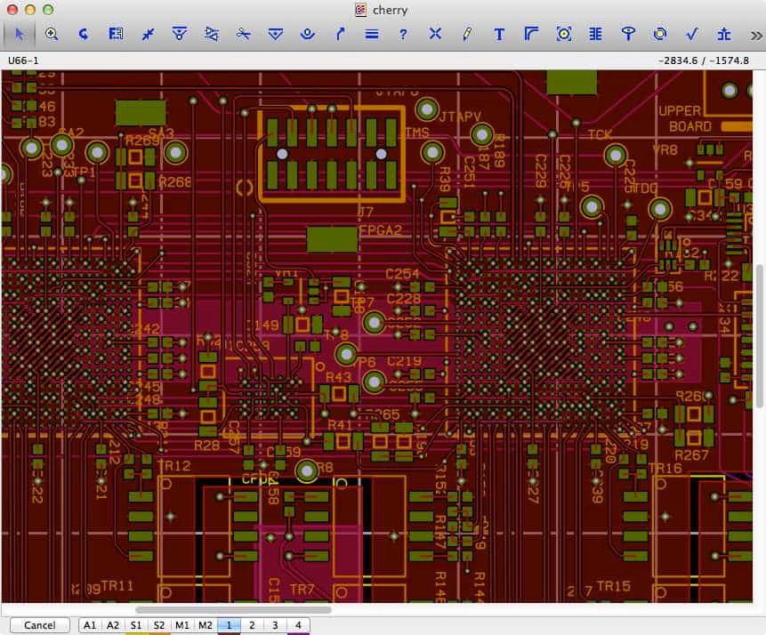
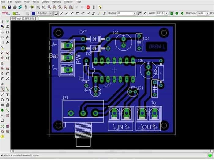
24. Open Circuit Design
Open Circuit Design provides free software for designing printed circuit board layouts. It has many features and is capable of professional-quality output. It is available for UN*X operating systems, e.g., GNU/Linux, Mac OS-X, or Cygwin under Windows. PCB was initially written by Thomas Nau of Ulm, Germany, and is now maintained by harry Eaton of the Johns Hopkins University Applied Physics Laboratory, Laurel, Maryland, USA.
PCB 3.0 is a branch of the source code modified to operate under the Tcl/Tk interpreter. Most of the coding for PCB 3.0 was done at MultiGiG, Inc., Scotts Valley, California, by Tim Edwards, Paramesh Santanam, and (working from India, courtesy of SynApps, Inc.), Nishit Patel. The codebase is a departure from the original PCB in that a complete Tcl command-line API was concocted for PCB, and the GUI was re-written as a Tk script. For the first cut (version 3.0), a fair bit of effort ensured that the GUI looks and acts as much as the original Xlib-based version.
Limitations:
- Windows operating Only
- layers: 8
25. gEDA

The gEDA project has produced and continues working on a full GPL'd suite and Electronic Design Automation tools toolkit. These tools are used for electrical circuit design, schematic capture, simulation, prototyping, and production. Currently, the gEDA project offers a mature suite of free software applications for electronics design, including schematic capture, attribute management, bill of materials (BOM) generation, net listing into over 20 netlist formats, analog, and digital simulation, and printed circuit board (PCB) layout.
26. FreePCB
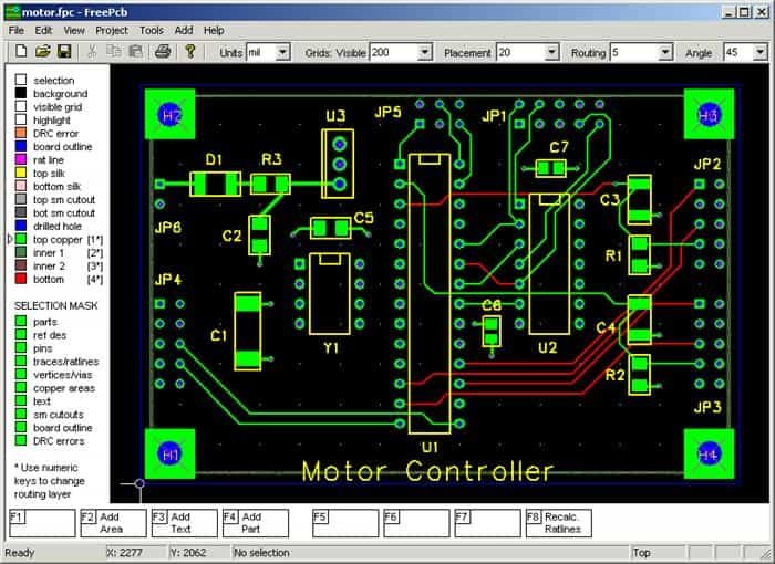
FreePCB is a free, open-source PCB editor for Microsoft Windows, released under the GNU General Public License. It was designed to be easy to learn and easy to use, yet capable of professional-quality work. It does not have a built-in autorouter, but it can use the FreeRoute web-based autorouter at www.freerouting.net. Some of its features are:
- 1 to 16 copper layers
- Board size up to 60 inches by 60 inches
- Uses English or metric units (i.e., mils or mm) for most functions.
- Footprint libraries courtesy of Ivex Design International, PCB Matrix, and the IPC.
- Copper fill areas
- Footprint Wizard and Footprint Editor for creating or modifying footprints
- Imports and exports PADS-PCB netlists
- Exports extended Gerber files (RS274X) and Excellon drill files
- Design rule checker
- Autosave
27. DesignSpark PCB
DesignSpark PCB is free to download and use and always will be.
DesignSpark PCB is here to help your company explore more design options – leading to increased innovation. This unique software's core is a powerful software engine that enables you to capture schematics and design PCB boards and layouts.
Critical features of DesignSpark PCB
- Seamless integration into existing design workflows
- No limitation on your schematic size
- No limitation on your PCB design!
- Create your libraries or use ours
- Output the files you want
- Create BOMs in the format you want
- Integration with PCB Part Library
28. KiCad
KiCad is an open-source software suite for Electronic Design Automation (EDA). The programs handle Schematic Capture and PCB Layout with Gerber output. The suite runs on Windows, Linux, and OS X and is licensed under GNU GPL v3. The first release date was in 1992 by its original author, Jean-Pierre Charras, but it is currently under development by the KiCad Developers Team.
Features:
- Schematic Capture
With the schematic editor, you can create your design without limit; there are no paywalls to unlock features. An official library for schematic symbols and a built-in schematic symbol editor help you get started quickly with your designs.
- PCB Layout
Make professional PCB layouts with up to 32 copper layers. KiCad now has a push and shove router capable of routing differential pairs and interactively tuning trace lengths.
- 3D Viewer
KiCad includes a 3D viewer, which you can use to inspect your design on an interactive canvas. You can rotate and pan around to inspect details that are difficult to inspect on a 2D view. Multiple rendering options allow you to modify the board's aesthetic appearance or hide and show features for easier inspection.
29. Eagle
EAGLE is a scriptable electronic design automation application with schematic capture, printed circuit board layout, auto-router, and computer-aided manufacturing features. EAGLE stands for Easily Applicable Graphical Layout Editor and is developed by CadSoft Computer GmbH. Autodesk Inc. acquired Cadsoft Computer GmbH in 2016.
EAGLE contains a schematic editor for designing circuit diagrams. Parts can be placed on many sheets and connected through ports.
The PCB layout editor allows back annotation to the schematic and auto-routing to connect traces based on the connections defined in the schematic.
EAGLE saves Gerber and PostScript layout files and Excellon and Sieb & Meyer drill files. Many PCB fabrication companies accept these standard files.
Features:
- Schematic Editor
The schematic editor allows you to create a symbolic easy-to-read representation of your design.
- Layout Editor
The layout editor brings your design to life.
The board represents the physical reality of your design.
- Autorouting
The autorouter is a helpful tool for placing copper traces between components.
- Export Gerber, BOM and SVG
The online export options allow you to export to various formats to share and manufacture your work.
- Pros and Cons:
Pros: Eagle CAD is easy for hobbyists just starting with printed circuit CAD designs and includes free options for limited tool versions.
Cons: This software is not mainstream with corporate businesses that have internal PCB designers. Also, using this tool for higher technology boards requires more manual calculations and routing than the higher-end CAD tools.
30. Tiny CAD
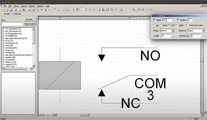
TinyCAD is a simple and basic electronic circuit diagram and PCB designer. This is open-source software. It's also often used for drawing single-line diagrams, flowcharts, and presentation drawings.
TinyCAD supports PCB layout programs with multiple connection list formats. It can also create SPICE simulation lists and comes with character libraries. This free PCB design software can also check the circuit design flaws.
Aside from the possibility to print your projects, you can use TinyCAD to publish your drawings by copying and pasting them into a Word document or saving them as a PNG bitmap image for the Internet. You can also use it as an interface for other PCB layout tools.
- Supports standard and custom libraries
- Checks design flaws
- You can print, copy or save drawings
- Printed circuit boards in several formats
- Only for Windows
Helpful Resources
Posted by: michaeladunckerssa.blogspot.com
Source: https://www.pcbelec.com/pcb-design-software-free-download


Komentar
Posting Komentar